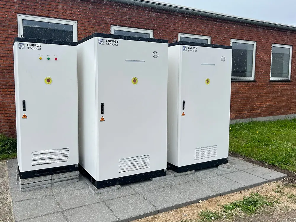
A grid-connected C&I BESS normally connects its battery cabinets to a bidirectional power conversion system, then to AC protection and switchgear, and finally to the facility electrical system at an approved connection point. Depending on system voltage and project size, a transformer may sit between the BESS and the utility network. An EMS coordinates charging and discharging, while meters, relays, breakers, and the grid operator’s requirements determine when and how power may flow. The exact arrangement cannot be selected from battery capacity alone: it must be engineered around the site’s load, voltage level, transformer capacity, export policy, protection study, operating objective, and local grid code.
For a project buyer, the practical question is not simply whether the battery can connect to the grid. It is whether the complete system can connect at the required power without overloading the site, violating import or export limits, weakening protection coordination, or creating control conflicts with solar PV, generators, EV chargers, or existing building loads.
The Basic Grid-Connected BESS Architecture
Simplified functional path. The EMS and protection system supervise multiple devices rather than sitting in the main power path.
During charging, power flows from the grid or on-site generation through the AC system and PCS into the battery. During discharge, the PCS reverses the process and supplies the site or, when permitted, exports power through the grid connection. The BMS protects the battery, the PCS controls electrical conversion, and the EMS decides when dispatch is allowed within project and warranty limits.
| Component | Main Role in Grid Connection | What the Buyer Should Confirm |
|---|---|---|
| Battery and BMS | Provide stored DC energy and define safe charge/discharge limits | Voltage range, current limits, usable SoC window, alarms and PCS interface |
| PCS | Convert DC to AC and AC to DC; control active and reactive power | Rated power, voltage, grid functions, efficiency boundary and applicable certification |
| EMS or site controller | Coordinate dispatch with meters, tariffs, PV, loads and grid limits | Control hierarchy, reserve rules, export limitation and fallback behavior |
| Switchgear and protection | Provide isolation, fault clearing, switching, protection and maintenance access | Ratings, short-circuit duty, selectivity, relay settings and operating sequence |
| Transformer | Match the BESS AC voltage to the facility or utility voltage where needed | Power rating, impedance, losses, vector group, grounding, harmonics and thermal duty |
| Metering | Measure import, export, site demand, BESS power and settlement data | Measurement point, accuracy, sign convention, sampling, communication and ownership |
1. Start With the Site, Not the Battery Cabinet
A project should begin with electrical and operating data from the site. A 400kW BESS can be appropriate for one facility and impossible to connect at another because the two sites may have different transformers, peak loads, fault levels, voltage conditions, export permissions, or spare breaker capacity.
The initial site package should normally include:
- Recent interval load data at a suitable time resolution
- Existing single-line diagrams and equipment schedules
- Utility supply voltage and contracted import or export limits
- Transformer ratings, loading, impedance, grounding and condition
- Main switchboard and feeder ratings
- Existing PV, generators, UPS, EV chargers, motors or other large loads
- Site power-factor, power-quality and outage information where relevant
- Planned future loads and expansion
- The commercial objective: peak shaving, solar use, backup, demand response, charging support or a combination
This information establishes the electrical boundary. It also prevents a common mistake: selecting battery energy in kWh without confirming how much PCS power in kW can actually pass through the site’s connection.
2. Define the Connection Point and Power Boundary
The connection point determines where the project measures power and where technical responsibility changes. A BESS may connect behind the facility meter, at a low-voltage switchboard, through a dedicated transformer to a medium-voltage bus, or as part of a combined solar-storage plant. The correct choice depends on project scale, voltage, existing infrastructure, ownership boundaries, grid requirements, and operating purpose.
The design team should document:
- The physical and contractual connection point
- The AC voltage and frequency
- Maximum permitted import and export
- Whether export is allowed, limited, or prohibited
- The point used to measure BESS power, energy and efficiency
- Who owns each breaker, transformer, meter, cable and control interface
- Which device has final authority to limit or disconnect the BESS
3. Decide Whether the Project Connects at Low or Medium Voltage
Low-Voltage Connection
Smaller C&I systems may connect directly to a suitable low-voltage distribution board. This can simplify the architecture, but only if the board, upstream transformer, cables, protection and utility service have enough capacity. The designer still needs to calculate load current, voltage drop, short-circuit conditions, protection coordination and the combined behavior of the BESS with existing loads.
Medium-Voltage Connection
Larger projects or sites with limited low-voltage capacity may connect through a step-up transformer and medium-voltage switchgear. This adds equipment and approval work but may provide a more appropriate connection for higher power. The project can require protection relays, utility-visible disconnects, plant control, reactive-power capability, power-quality studies and formal certification or commissioning evidence.
Voltage level should be decided through engineering and utility consultation. It should not be chosen from a generic power threshold because network rules, site topology and utility practice differ.
4. Select the PCS Around the Grid and Duty Profile
The PCS is the primary electrical interface between the battery and AC system. Its selection affects usable power, grid-code functions, reactive-power capability, harmonics, efficiency, voltage range, fault response and control performance.
PCS evaluation should include:
- Continuous and short-duration power requirements
- Battery DC voltage range across SoC and temperature
- AC voltage and transformer arrangement
- Active and reactive power capability
- Power factor and voltage-control requirements
- Frequency and voltage ride-through behavior where required
- Anti-islanding and reconnection functions
- Harmonic and power-quality requirements
- Communication with BMS, EMS and plant controller
- Applicable safety and grid-interconnection certification for the destination market
A PCS certificate is not the same as project approval. The exact certified model, firmware, settings, transformer, protection scheme and plant behavior must still match the connection agreement.
5. AC-Coupled and DC-Coupled Connections Serve Different Projects
In an AC-coupled project, the BESS and PV system normally have separate power converters and meet on the AC side. This is common for retrofits, projects with existing PV, and sites that need independent control of storage and generation.
In a DC-coupled project, PV and battery share part of the DC architecture before conversion to AC. It can reduce some conversion steps and capture energy that might otherwise be curtailed, but it requires compatible equipment, coordinated controls and careful definition of ratings and test boundaries.
This article focuses on grid interconnection rather than architecture selection. Buyers comparing the two arrangements can use PVB’s AC-Coupled vs DC-Coupled BESS Guide.
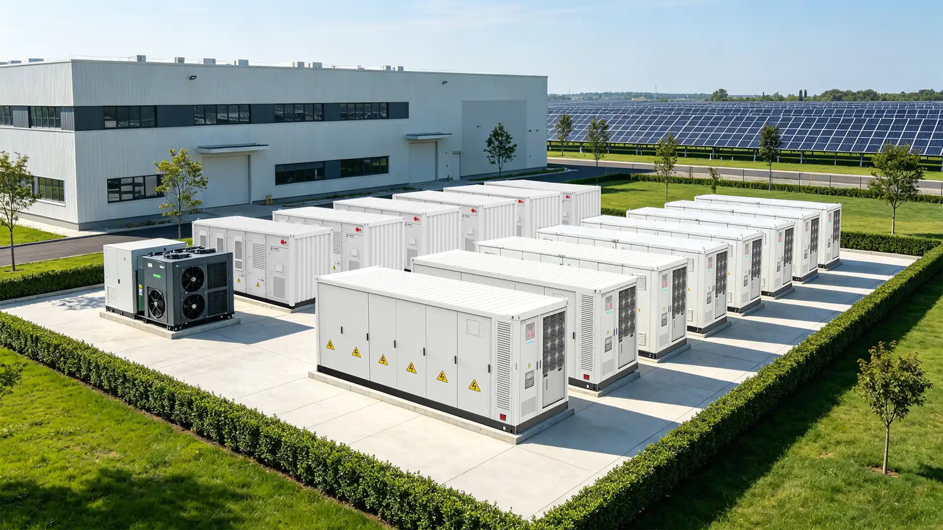
6. Design the Transformer, Switchgear and Cables as One System
The transformer is not sized by copying the PCS nameplate into a quotation. The engineer should consider maximum simultaneous power, reactive-power duty, ambient conditions, cooling method, harmonic loading, impedance, losses, inrush, voltage regulation, grounding and the possibility of future expansion. If the transformer also serves site loads or solar generation, the combined operating cases become more important.
Switchgear and cables must be rated for normal current and credible fault conditions. Protection devices need sufficient interrupting capability and a coordinated sequence so that the closest suitable device clears a fault without unnecessarily disconnecting the entire site.
The final design can include:
- AC combiner or parallel cabinet for multiple PCS units
- Main BESS breaker and lockable isolation
- Low-voltage or medium-voltage switchgear
- Protection relays and current or voltage transformers
- Revenue, compliance or control metering
- Step-up or isolation transformer where required
- Auxiliary power distribution for HVAC, controls and safety systems
- Earthing, bonding and surge protection
7. Protection Coordination Is a Project-Level Task
Protection should detect abnormal conditions, isolate the appropriate equipment and coordinate with the utility and facility system. Because inverter-based resources behave differently from rotating generators, protection studies should use data appropriate to the selected PCS rather than assuming conventional generator fault current.
Depending on the jurisdiction and connection, the scheme may address overcurrent, earth fault, voltage, frequency, anti-islanding, directional power, transformer protection, synchronism, breaker failure, emergency shutdown and utility trip signals. This list is illustrative, not a universal relay schedule.
The project engineer and network operator should agree on:
- Required protective functions
- Measurement locations and relay inputs
- Trip targets and breaker logic
- Settings, delays and coordination margins
- Reconnection conditions
- Testing, witness and documentation requirements
8. The EMS Must Coordinate the Entire Site
A BESS can be electrically connected yet commercially ineffective if the EMS uses the wrong data or priority. The controller should know the site’s real-time demand, utility import or export, PV production, battery limits, tariff periods, reserve requirement and any large flexible loads.
A sensible control hierarchy might be:
- Respect battery, PCS, electrical and site safety limits.
- Respect the utility’s import, export and operating constraints.
- Protect required backup reserve.
- Manage transformer or feeder demand.
- Optimize solar self-consumption, tariffs or other commercial objectives.
Actual priorities depend on the project. A data center may protect reserve before savings, while a factory may place greater emphasis on demand control. An EV charging site may require rapid response to charger demand while preserving enough energy for later operating periods.
The EMS should also have a defined behavior for missing data, frozen meter values, lost communication, controller restart, time synchronization failure and unavailable battery blocks. These degraded modes belong in the commissioning plan.
9. What Grid Studies May Be Required?
The network operator or project engineer may request studies before approving connection. Scope depends on system size, voltage, local rules and network conditions. Possible studies include:
- Load flow and voltage variation
- Short-circuit contribution and equipment duty
- Protection coordination
- Power quality and harmonic assessment
- Voltage step, flicker or rapid voltage change
- Reactive-power and power-factor capability
- Dynamic response, ride-through or stability for larger projects
- Transformer thermal loading and losses
- Export limitation or reverse-power behavior
- Earthing and touch or step potential where applicable
The study model must match the proposed equipment. Using a generic inverter model or outdated firmware information can produce an approval that does not represent the delivered project.
10. The Grid Connection Process, Step by Step
Set the commercial objective, required power, usable energy, reserve, cycling and expansion plan.
Collect load data, drawings, transformer and switchgear information, utility limits and existing DER details.
Select the preliminary voltage level, connection point, PCS arrangement, transformer and operating mode.
Submit the required application data and confirm studies, certificates, controls, protection and witness requirements.
Finalize the single-line diagram, cable and equipment ratings, protection, metering, EMS logic and civil interfaces.
Match the ordered BESS, PCS, firmware, options and documents to the approved project design.
Verify the manufactured configuration, then install it under approved procedures and manufacturer instructions.
Test real meters, controls, protection, grid functions, operating modes and handover requirements.
11. What Should Be Tested Before Commercial Operation?
Factory acceptance testing can confirm the manufactured system and available simulated interfaces. Site acceptance and commissioning must then prove the installed project. The exact plan should be agreed before installation and aligned with the connection agreement.
Site testing can include:
- Inspection against approved drawings and equipment records
- Grounding, insulation and cable checks
- Breaker, relay, interlock and emergency-stop testing
- Meter direction, scaling, timestamps and data quality
- BMS, PCS, EMS and utility-control communication
- Charge and discharge at agreed power levels
- Import and export limit response
- Reactive-power or power-factor functions where required
- Loss-of-grid, anti-islanding and reconnection behavior according to the approved procedure
- Fallback behavior after meter, controller or communication failure
- Integration with PV, generators, EV chargers or site loads
- Baseline efficiency, energy and thermal data where included in acceptance
Testing should use measurable pass criteria. “The BESS ran successfully” is not enough. Reports should record the configuration, conditions, expected response, actual response, data, deviations and approvals.
12. Illustrative PVB C&I Connection Example
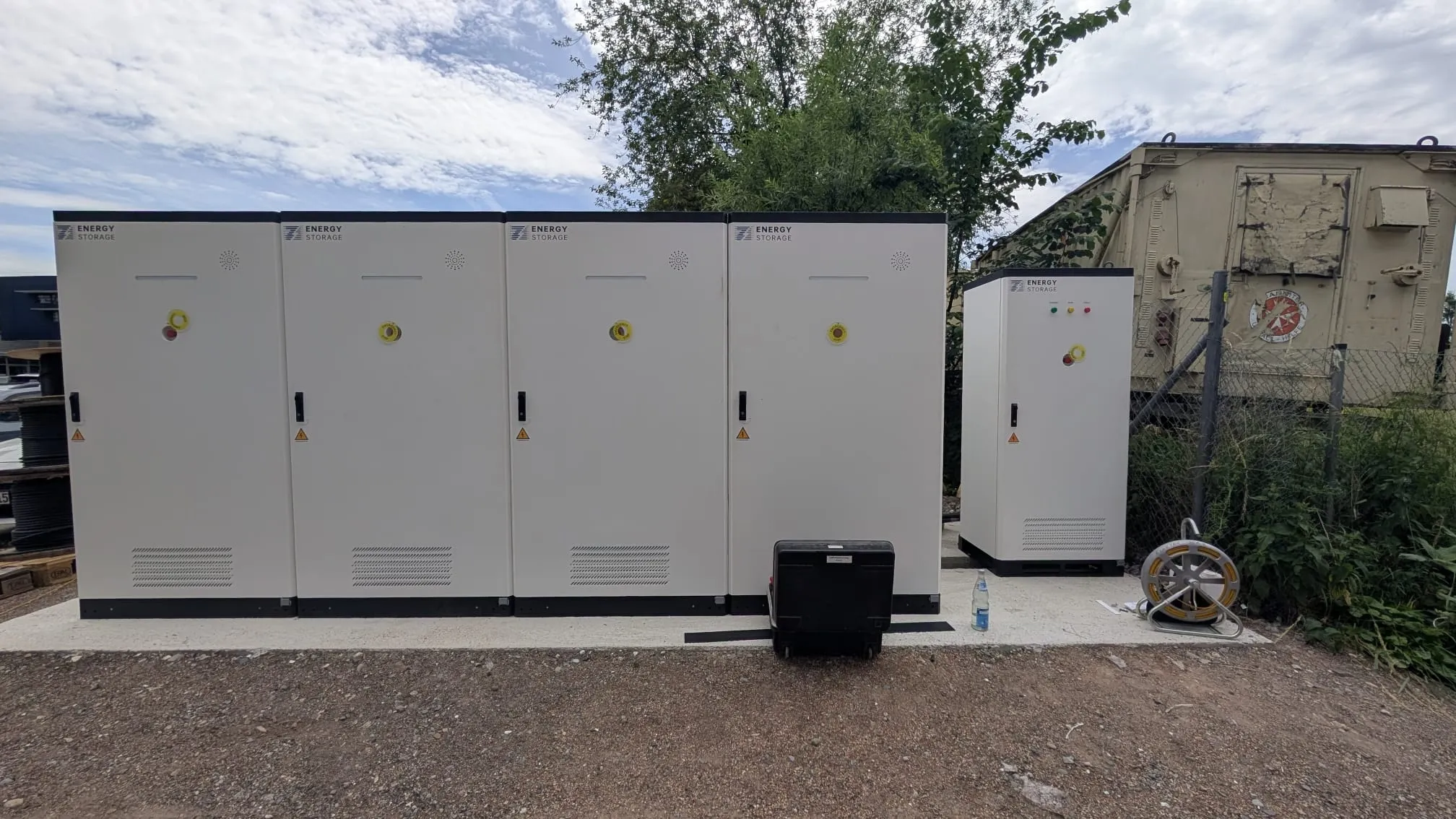
Consider four PVB 100kW/241kWh air-cooled cabinets. At published nameplate values, the storage block totals 400kW and 964kWh. Multiple units can be combined through an AC parallel or distribution arrangement, with a site EMS coordinating the blocks.
A preliminary architecture could be:
- Four 100kW/241kWh BESS cabinets
- One AC parallel cabinet or appropriately engineered low-voltage switchboard
- Site meter at the agreed control boundary
- EMS connection to BESS blocks and facility metering
- Step-up transformer and medium-voltage switchgear if required by the site connection
- Utility-approved protection, export control and commissioning process
This is an illustrative configuration, not a construction design. The correct transformer, cable, breaker, protection and operating limits require site calculations. Four cabinets do not automatically guarantee 400kW at the grid connection under every temperature, SoC, voltage, reactive-power or failure condition.
13. Regional Rules: Examples, Not a Universal Checklist
International standards can provide a common technical foundation, but grid interconnection is implemented through regional and utility-specific rules.
| Market Example | Relevant Framework | Practical Meaning |
|---|---|---|
| International planning | IEC 62933-3-1:2025 | Addresses planning, sizing, functions, performance assessment, monitoring, information exchange, operation and maintenance for grid-connected electrical energy storage systems. |
| United States | IEEE 1547 series, UL 1741 and utility interconnection rules | DER performance, interoperability, abnormal-condition response, power quality, testing and certified interconnection equipment are important, but local utility procedures still apply. |
| Germany | VDE-AR-N 4105 or VDE-AR-N 4110 depending on connection level, plus network-operator requirements | Low- and medium-voltage projects follow different technical connection rules. Storage and combined generation/load/storage facilities are explicitly addressed in the medium-voltage framework. |
| Other markets | National standards, distribution codes and utility-specific procedures | The project team must identify the current adopted rules, required certificates, studies and approval authority before equipment is ordered. |
14. Documents a Buyer Should Request
- Project single-line diagram showing the connection point and ownership boundary
- BESS, PCS, transformer, switchgear and meter datasheets
- Applicable product certificates and grid-compliance records for the exact model
- PCS capability curve and control-function information
- Protection philosophy, relay schedule and approved settings
- Load-flow, short-circuit, harmonic or other studies required by the project
- EMS functional description and import/export control logic
- Communication architecture and point list
- Utility application, comments, conditions and approval records
- FAT, SAT and commissioning plans and reports
- As-built drawings, firmware and final configuration records
- Operating, maintenance, emergency and warranty documentation
15. Common BESS Grid Connection Mistakes
- Buying the battery before confirming the connection point and utility capacity
- Sizing only in kWh and ignoring the required kW and duration
- Assuming the existing transformer has spare capacity without interval data or thermal review
- Treating PCS certification as automatic approval of the complete project
- Ignoring reactive-power duty when sizing the PCS or transformer
- Using generic fault-current assumptions for inverter-based equipment
- Failing to define meter-loss or communication-loss behavior for export limitation
- Allowing PV, BESS, EV chargers and generators to operate under separate, conflicting controls
- Submitting one equipment configuration and delivering another model or firmware version
- Leaving utility engagement until construction is nearly complete
- Testing individual devices without an integrated site operating sequence
- Handing over the project without final settings, reports and configuration backups
How PVB Supports Grid-Connected C&I BESS Projects
PVB supplies commercial and industrial battery energy storage products for applications including peak shaving, solar self-consumption, backup support, capacity management, microgrids and EV charging integration. Depending on the selected model and project scope, PVB can support equipment configuration, interface information, communication coordination, factory testing, installation guidance, commissioning support and after-sales service.
PVB’s 100kW/241kWh air-cooled system is published as an all-in-one LFP C&I cabinet supporting CAN, RS485 and TCP/IP communication and multi-level parallel connection. Larger projects can also evaluate PVB liquid-cooled cabinet and containerized solutions according to required power, energy, site conditions and market requirements.
PVB does not replace the local network operator, EPC, electrical designer, protection engineer or authority. The strongest project result comes when the supplier receives the connection requirements early enough to match the BESS and PCS configuration to the approved site design.
Related PVB Guides
FAQ: Connecting a C&I BESS to the Grid
How does a BESS connect to the electrical grid?
A BESS normally connects its battery cabinets to a bidirectional PCS, then through AC protection and switchgear to the facility electrical system. A transformer may be required to match voltage. The EMS, meters and protection system coordinate power flow at the approved grid connection point.
Can a BESS connect directly to a low-voltage switchboard?
It can when the switchboard, transformer, cables, protection and utility service are suitable for the proposed power and fault conditions. The design still requires load, voltage-drop, short-circuit, protection and operating review by qualified professionals.
When does a BESS need a transformer?
A transformer is generally needed when the PCS output voltage does not match the facility or utility connection voltage, or when the project uses a dedicated medium-voltage connection. Its rating and design depend on power, reactive duty, harmonics, losses, impedance, grounding, ambient conditions and expansion plans.
Can a grid-connected BESS operate during a power outage?
Not automatically. Backup or island operation requires a system specifically designed for it, including grid isolation, a grid-forming source or suitable controls, protected loads, switchgear, protection and an approved operating sequence. A standard grid-following BESS may shut down when the grid is lost.
Can a BESS export electricity to the grid?
Only when the utility connection agreement and local rules permit it. Some projects allow export, some impose a fixed limit and others require zero export. The EMS, meter, PCS and fallback logic must implement the approved condition.
What is the difference between the PCS and EMS in grid connection?
The PCS performs bidirectional electrical conversion and executes power commands within its operating limits. The EMS decides when and how much the BESS should charge or discharge based on site demand, battery limits, tariffs, PV, reserve and grid constraints.
Which standards apply to a grid-connected BESS?
The answer depends on the country, voltage level, system size and network operator. Examples include IEC 62933 planning and performance standards, IEEE 1547 and UL 1741 in the United States, and VDE-AR-N 4105 or VDE-AR-N 4110 in Germany. Current local adoption and project-specific requirements must be confirmed.
What should be tested before a BESS is allowed to operate?
The approved commissioning plan may include electrical inspection, grounding and insulation, protection and interlocks, meter direction and scaling, communications, charge and discharge, import or export control, reactive-power functions, loss-of-grid response, reconnection, fallback behavior and integration with site equipment.
Sources and Further Reading
- International Electrotechnical Commission — IEC 62933-3-1:2025, Planning and Performance Assessment of Electrical Energy Storage Systems. Accessed August 5, 2026.
- IEEE Standards Association — IEEE Standard for Interconnection and Interoperability of Distributed Energy Resources. Accessed August 5, 2026.
- UL Solutions — PV Inverter and BESS Converters Certification. Accessed August 5, 2026.
- VDE FNN — Technical Connection Rules for Medium Voltage, VDE-AR-N 4110. Accessed August 5, 2026.
- VDE FNN — Technical Connection Rules and Documents. Accessed August 5, 2026.
- PVB — 100kW/241kWh Air-Cooled Energy Storage System. Accessed August 5, 2026.