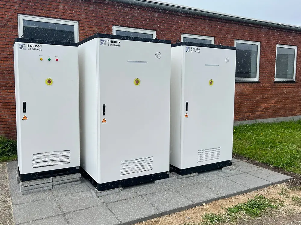
A commercial and industrial BESS is manufactured by integrating battery cells and modules, BMS, PCS, EMS, thermal management, electrical protection, fire-safety functions, communication hardware, and the enclosure into one controlled system. A credible manufacturer then verifies the delivered configuration through traceable inspections, functional checks, protection tests, communication tests, and the factory acceptance tests agreed for the project. For buyers, the important result is not simply that the cabinet powers on. It is that the system can be matched to its drawings, settings, serial numbers, test records, and approved operating limits.
That distinction matters. Two battery cabinets can look almost identical from the outside while differing substantially in component control, wiring quality, software configuration, thermal behavior, documentation, and test evidence. This guide follows a C&I BESS from design freeze to shipment and explains what a buyer should expect to see at each stage.
The Short Answer: What Should a BESS Manufacturer Prove?
| Production Stage | What Should Be Controlled | Evidence a Buyer Can Request |
|---|---|---|
| Design freeze | Power, energy, voltage, operating mode, interfaces, environment, grid and site requirements | Approved datasheet, single-line diagram, interface list, compliance matrix |
| Incoming inspection | Component identity, quantity, condition, supplier records, ratings, traceability | Inspection records, serial or batch records, approved bill of materials |
| Assembly | Mechanical fit, electrical connections, cable routing, torque, grounding, labels | Process inspection records, torque records where specified, photographs |
| Integration | BMS, PCS, EMS, meters, HMI, thermal control, protection and communications | Configuration list, firmware list, I/O or point list, alarm matrix |
| Factory testing | Startup, commands, interlocks, alarms, protection response and agreed performance checks | Signed FAT report, test data, deviations, punch list and retest records |
| Release and shipment | Final configuration, packaging, transport condition, documentation and preservation | Release note, packing list, transport documents, manuals and handover index |
1. Manufacturing Starts Before the Production Line
The first manufacturing decision is not where to place a cable. It is what the system must actually do. A BESS intended for daily peak shaving has a different duty profile from a backup system, an EV charging support system, or a solar self-consumption project. The project team needs to define the electrical boundary, usable energy requirement, power duration, expected cycling, ambient conditions, communication interfaces, grid constraints, and reserve strategy before the build is released.
A practical design freeze should answer questions such as:
- What are the required rated power and energy, and where are they measured?
- How much energy must remain available after reserve, SoC limits, conversion losses, and auxiliary consumption?
- Will the system operate grid-connected, in backup mode, or in a hybrid arrangement?
- Which site controller, meter, PV inverter, generator, charger, or SCADA platform must exchange data with the BESS?
- What temperature, humidity, altitude, corrosion, dust, and enclosure conditions apply?
- Which standards, declarations, transport requirements, grid rules, and local approvals apply to the exact model and destination?
If these points are still unclear when production begins, the factory may build a technically sound cabinet that is wrong for the project. Good manufacturing therefore starts with controlled requirements and a documented configuration.
2. Incoming Components and Traceability
A BESS manufacturer depends on a chain of cells, battery modules, contactors, fuses, sensors, cables, connectors, breakers, power electronics, cooling components, fire-safety devices, meters, controllers, and enclosure parts. Incoming inspection is used to confirm that received parts match the approved specification and are suitable for release into production.
The inspection depth varies by component and quality plan. Common checks can include:
- Supplier, model, rating, quantity, batch number, and physical condition
- Dimensional or connector compatibility where required
- Documentation, declaration, or certificate status for controlled components
- Battery cell or module data needed for matching and traceability
- Storage conditions and shelf-life controls for sensitive parts
- Nonconformance identification, segregation, review, and disposition
Traceability is commercially important because a future alarm or warranty investigation may begin with a serial number. The buyer should be able to connect the delivered cabinet to the relevant product record, configuration, firmware, and major component identity without relying on memory or informal messages.
3. Battery Module, Rack, and Cabinet Assembly
During assembly, battery modules are installed into racks or cabinet positions and connected through the designed high-voltage and low-voltage architecture. Mechanical restraint, clearance, cable routing, connector engagement, polarity, insulation, grounding, and service access all matter. A loose connection can create heat. An incorrectly routed cable can introduce wear or obstruct maintenance. A missing label can turn a future service task into avoidable risk.
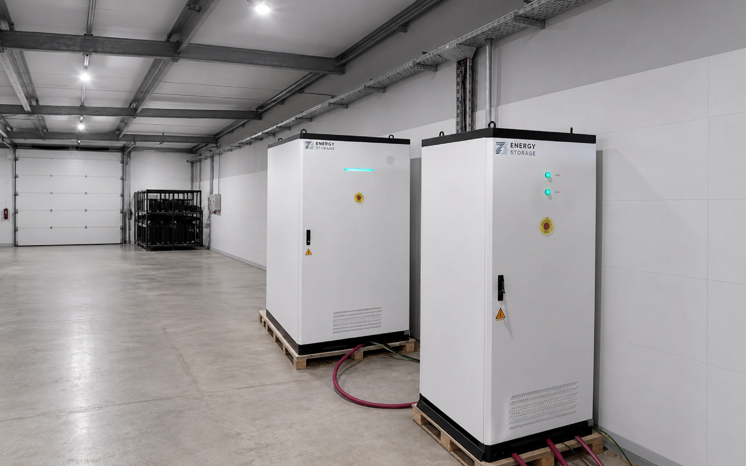
Cabinet structure, doors, seals, mounting points, module restraint, clearances, airflow paths, lifting and service access.
Polarity, busbars, cables, connectors, protection devices, grounding, insulation separation and terminal identification.
Sensors, BMS harnesses, auxiliary supply, control wiring, communication wiring and I/O termination.
Inspection status, controlled work instructions, required torque or check records, deviations and rework approval.
4. Integrating the BMS, PCS, EMS, and Site Interfaces
The battery is only one part of a working BESS. The BMS, PCS, and EMS must exchange the right data and respect the same operating limits.
Battery Management System
The BMS monitors battery conditions and enforces battery-side limits. Depending on the design, this includes cell and module voltage, temperature, current, state of charge, state of health, insulation status, contactor control, alarms, and permitted charge or discharge power. The PCS or EMS should not continue requesting power that the BMS has limited for safety or battery protection.
Power Conversion System
The PCS converts energy between the battery DC bus and the site AC system. Factory integration should confirm the applicable voltage range, command path, operating modes, protection coordination, active and reactive power functions, and response to BMS limits or communication loss.
Energy Management System
The EMS coordinates the system-level objective. It may schedule peak shaving, solar charging, backup reserve, demand control, or EV charging support. The factory configuration should reflect the approved project logic, but final site values often require adjustment during commissioning because actual meters, tariffs, grid limits, and connected equipment are only available on site.
Communication
Communication checks should verify more than whether a cable is connected. The team needs to confirm addresses, scaling, units, timestamps, status definitions, alarms, command permissions, and fallback behavior. A value can appear on a dashboard and still be wrong if a sign convention, multiplier, or point mapping is incorrect.
5. Electrical Workmanship Checks
Before energization, the assembled system is inspected against drawings and work instructions. The exact checklist depends on the product, but it commonly covers:
- Correct component models and ratings
- Connection completeness and polarity
- Cable routing, bending, support, separation, and identification
- Terminal or busbar tightness according to the controlled assembly process
- Protective grounding and bonding
- Insulation and clearance condition
- Fuse, breaker, disconnect, contactor, and emergency-stop arrangement
- Door, seal, ventilation, cooling, drainage, and enclosure condition
- Safety, electrical, transport, and operating labels
This is not glamorous work, but it is one of the strongest indicators of manufacturing discipline. Software cannot compensate for a poor physical connection, and a certificate cannot replace inspection of the delivered unit.
6. Functional Testing Before Shipment
Functional testing checks whether the integrated system behaves as intended. The FAT should define the available power source, simulated inputs, test equipment, preconditions, measurement boundary, pass criteria, and witness requirements.
Depending on the agreed scope, factory checks may include:
- Power-up and controlled shutdown
- Local HMI operation and user access
- Charge, discharge, standby, stop, and reset commands
- Contactor, breaker, auxiliary supply, cooling, and fan or pump operation
- Sensor plausibility and key meter readings
- Alarm generation, severity, timestamp, acknowledgment, and reset
- Emergency-stop and selected protection interlocks
- BMS-to-PCS limit response
- EMS commands and remote communication points
- Behavior after selected communication or sensor failures
- Restoration after a controlled fault or interruption
7. Charge, Discharge, Power, and Energy Verification
Buyers often ask whether a BESS receives a complete charge-discharge test before shipment. There is no universal answer. The selected method depends on the product, factory equipment, test duration, production plan, contract, and FAT requirements. Some projects require a complete capacity or performance test. Others use partial cycling, power checks, simulated controls, component records, or sample-based verification.
When performance is tested, the report should state:
- Whether the measurement is on the DC side or at the AC point of connection
- Initial and final SoC and the permitted SoC window
- Charge and discharge power
- Test duration and energy measured
- Ambient, battery, and cooling conditions
- Whether auxiliary consumption is included
- The accuracy and status of test instruments where applicable
- Any derating, interruption, alarm, or excluded period
Nameplate energy is not automatically the same as usable AC energy. Reserve settings, battery operating limits, conversion losses, auxiliary loads, temperature, aging, and measurement boundary all affect the energy that a site can use. A buyer should therefore avoid comparing a DC nominal capacity from one supplier with an AC delivered-energy figure from another.
8. Thermal Management Verification
Temperature uniformity and thermal control affect performance, lifetime, power availability, and warranty compliance. Air-cooled and liquid-cooled systems use different components, but both require a defined control strategy and verified sensor response.
Factory verification may confirm fan, compressor, pump, valve, heater, coolant, or HVAC operation as applicable to the selected design. It should also check temperature data, alarm thresholds, control commands, and the response to abnormal conditions that can be tested safely at the factory.
A short FAT at room temperature cannot prove years of performance in every climate. Environmental ratings and published operating limits should be supported by the applicable product design evidence, while the project team must still confirm ventilation, clearance, solar exposure, altitude, ambient range, and maintenance access for the real site.
9. Safety Functions and Protection Tests
BESS protection is layered. Battery limits, electrical protection, thermal control, enclosure design, alarms, emergency functions, and site fire-safety measures have different jobs. The factory should verify the functions assigned to the delivered equipment, while the site team is responsible for installation-level design and approval.
Agreed checks may cover:
- Overvoltage, undervoltage, overcurrent, temperature, and insulation alarms or limits
- Emergency-stop logic and controlled isolation
- Loss of communication between key controllers
- Selected sensor-failure or plausibility conditions
- PCS response to a BMS limit or trip
- Fire-detection or suppression interface signals where included
- Alarm transmission to the local HMI or agreed remote endpoint
- Restart permissions after a fault
Testing must follow approved procedures. Safety devices should not be defeated casually to create a demonstration. Some protective functions are verified by simulation, signal injection, documented component evidence, or controlled test methods rather than by creating a hazardous physical condition.
10. FAT and SAT Are Not the Same
| Factory Acceptance Test | Site Acceptance Test |
|---|---|
| Performed before shipment or release | Performed after installation at the project site |
| Verifies the manufactured configuration and available factory functions | Verifies the installed condition and real site interfaces |
| Can use simulated meters, signals, loads, or controllers | Uses actual switchgear, meters, network, EMS, PV, generator, chargers, or site controls as applicable |
| Finds production, configuration, and integration issues before transport | Finds installation, wiring, addressing, grid, communication, and sequence issues |
| Does not prove the completed site will operate correctly | Does not replace long-term monitoring, maintenance, or performance guarantees |
A strong project uses both. FAT reduces the risk of shipping an incomplete or incorrectly configured system. SAT confirms that the equipment works inside the real electrical and operational environment. The O&M plan then preserves the accepted condition after handover.
11. What Documents Should the Buyer Receive?
A BESS is not fully handed over when the truck leaves the factory. The documentation package should allow the owner, EPC, installer, commissioning team, and service provider to identify, install, test, operate, and support the delivered configuration.
- Approved product datasheet and project configuration
- Single-line diagram and applicable electrical drawings
- General arrangement, dimensions, weight, lifting, clearance, and foundation information
- Communication protocol, point list, addressing, units, and command permissions
- Alarm, protection, and operating-limit information
- Operation, installation, maintenance, troubleshooting, and emergency instructions
- Applicable certificates, declarations, reports, and model references
- UN38.3-related transport documentation where required for shipment
- FAT report, deviations, punch list, corrective actions, and retest evidence
- Serial numbers, firmware versions, settings, and configuration backups as agreed
- Recommended spare parts and consumables
- Warranty conditions, exclusions, data requirements, and claim process
12. A PVB 100kW/241kWh C&I BESS Example
PVB’s published 100kW/241kWh air-cooled energy storage system is an all-in-one C&I cabinet based on LFP battery technology. The public product page lists an IP55 enclosure, operating temperature from -30°C to +50°C, system efficiency of at least 90%, CAN, RS485, and TCP/IP communication, and support for multi-level parallel connection.
The model is positioned for applications such as peak shaving, capacity support, emergency backup, and grid or renewable-energy coordination. These published values help a buyer form an initial shortlist. They do not replace project engineering or the need to confirm the exact quotation, usable-energy boundary, selected options, parallel-control architecture, certification package, FAT scope, and site acceptance criteria.

13. How Manufacturing Changes for Different C&I Applications
A factory does not need a completely different production line for every use case, but the approved configuration and controls can change substantially.
Factory Peak Shaving
The design must reflect the site’s peak demand, tariff window, transformer limit, expected cycling, and power-control response. Meter integration and EMS logic are central to the acceptance plan.
Solar Self-Consumption
The BESS should coordinate with PV generation, export limits, site demand, and curtailment rules. Forecasting may be added at the site-control level, but the underlying battery limits must remain protected.
EV Charging Support
High-power chargers can create short, steep demand changes. The BESS and site controller must coordinate charger requests, grid import limits, reserve requirements, and available battery power rather than assuming the storage system can supply every charger at full nameplate output simultaneously.
Backup and Data Centers
Backup projects require a clear critical-load boundary, reserve hierarchy, transfer sequence, runtime target, and integration plan for UPS, generators, switchgear, and monitoring. Economic dispatch should not consume protected reserve unless the approved operating strategy allows it.
14. What Factory Testing Proves and What It Does Not
Factory testing can prove that the tested configuration met defined acceptance criteria under stated conditions. It can verify build quality, control logic, alarms, interfaces, protection behavior, and selected performance points before shipment.
It does not automatically prove:
- Approval by the local authority, grid operator, insurer, or fire authority
- Correct installation at the final site
- Lifetime capacity retention or annual availability
- Performance under every possible ambient or load condition
- Compatibility with untested third-party equipment or future software changes
- That the operator will maintain the system inside warranty limits
This is why buyers should connect manufacturing evidence to safety and certification review, commissioning, operating data, maintenance, and the BESS warranty.
15. Questions to Ask Before Approving a BESS for Production
- Which drawings, datasheets, and interface documents define the production configuration?
- What is the difference between nominal DC energy and usable AC energy for this project?
- Which components and serial or batch records are traceable?
- What checks are performed on every unit, and what checks are sample-based?
- Will the FAT include a full cycle, partial cycle, power test, simulation, or another method?
- Where will power, energy, and efficiency be measured?
- Are auxiliary loads included in the reported performance?
- Which alarms, interlocks, and communication-loss cases will be demonstrated?
- Which third-party devices or protocols are included in the factory integration test?
- What FAT evidence will be delivered, and can the buyer or an appointed engineer witness it?
- How are failed tests, deviations, rework, and retests documented?
- Which certificates and reports apply to the exact model and configuration?
- What remains to be tested during SAT and commissioning?
- Which firmware, settings, and configuration files will be recorded at handover?
- What installation, commissioning, training, spare-parts, and service support is included in the contract?
How PVB Supports C&I BESS Projects
PVB provides commercial and industrial energy storage products and project support for applications including factories, logistics sites, data centers, renewable-energy integration, microgrids, and EV charging. Depending on the selected product and contract, support can include product data, configuration coordination, interface information, factory test planning, installation and commissioning guidance, maintenance support, and after-sales service.
PVB’s public company information lists TÜV, CE, CB, RoHS, and UN38.3 certifications as well as ISO 9001 and ISO 14000 management-system certification. Certification remains product- and market-specific. Buyers should request the latest documents for the exact model, rating, component combination, and destination before treating a general company credential as project approval.
The useful question is not simply, “Does PVB manufacture BESS?” It is, “Can PVB document how the selected BESS is configured, tested, delivered, commissioned, and supported for this project?” That is the level at which a manufacturer becomes a reliable project partner.
Related PVB Guides
FAQ: C&I BESS Manufacturing and Factory Testing
What is BESS manufacturing?
BESS manufacturing is the controlled process of assembling and integrating batteries, BMS, PCS, EMS, thermal management, electrical protection, safety functions, communications, and the enclosure into a documented energy storage system. It also includes inspections, configuration control, testing, release, and handover records.
What is a BESS factory acceptance test?
A BESS factory acceptance test, or FAT, verifies agreed aspects of the manufactured system before shipment. Depending on the contract, it may include configuration review, startup, controls, alarms, interlocks, communications, protection response, and selected charge, discharge, power, or energy tests.
Does every BESS receive a full capacity test before shipment?
Not necessarily. The method can include a full cycle, partial cycle, power test, simulation, component evidence, or sample-based verification. The project FAT plan should state which tests apply to each unit, which are sampled, how measurements are taken, and what constitutes acceptance.
What is the difference between FAT and SAT?
FAT is performed before shipment to verify the manufactured configuration and available factory functions. SAT is performed after installation to verify the real site condition, wiring, grid connection, meters, communications, control sequences, and interfaces. Neither one should be assumed to replace the other.
What documents should a C&I BESS buyer receive?
The package should include the approved product configuration, drawings, installation and operation manuals, interface and alarm information, applicable model-specific compliance documents, FAT results, serial and firmware records as agreed, warranty terms, and the information needed for SAT, commissioning, maintenance, and support.
Is UN38.3 an approval to install and operate a BESS?
No. UN38.3 addresses lithium battery transport testing and classification. It is important for shipment, but it does not replace product safety assessment, grid approval, fire review, electrical installation rules, insurer requirements, or local authority approval.
How long does BESS factory testing take?
There is no single duration. It depends on the model, number of units, test equipment, configuration, witness requirements, performance-test scope, fault scenarios, and retesting. A full energy cycle takes longer than functional and simulated checks, so timing should be agreed in the FAT plan.
Can PVB customize a BESS for a C&I project?
PVB can support project configuration and application coordination for selected C&I energy storage products. The available power, energy, enclosure, communication, parallel operation, certification, control, FAT, commissioning, and service options should be confirmed for the exact product and contract.
Sources and Further Reading
- PVB — 100kW/241kWh Air-Cooling Energy Storage System. Accessed July 30, 2026.
- PVB — About PVB and Published Company Certifications. Accessed July 30, 2026.
- International Electrotechnical Commission — IEC 63056: Secondary Cells and Batteries Containing Alkaline or Other Non-Acid Electrolytes. Accessed July 30, 2026.
- United Nations Economic Commission for Europe — UN Manual of Tests and Criteria, Eighth Revised Edition and Amendment 1, including lithium battery subsection 38.3. Accessed July 30, 2026.
- International Organization for Standardization — ISO 9001:2015 Quality Management Systems Requirements. Accessed July 30, 2026.