Not always. If the BESS and the factory switchboard operate at the same voltage, and the existing electrical system has enough capacity, the BESS may connect without a new transformer.
If a low-voltage BESS must connect to a medium-voltage network—such as 10 kV, 11 kV or 20 kV—it will normally need a step-up transformer. Some packaged BESS solutions already include that transformer.
| Typical situation | New transformer? |
|---|---|
| 400 V BESS connecting to a suitable 400 V factory switchboard | Possibly not |
| 400 V BESS connecting to a 10–20 kV network | Usually yes |
| Packaged BESS with a built-in transformer and MV equipment | Already included |
| Existing transformer has insufficient capacity or cannot accept reverse power | A new or upgraded transformer may be needed |
The final answer depends on the BESS power, site voltage, existing transformer loading, charging and discharging conditions, fault level and local grid rules.
The battery’s MWh rating tells you how long it can run. It does not tell you how large the transformer or breaker must be. For example, a 2 MWh battery with a 500 kW PCS moves no more than roughly 500 kW at one time, while a smaller battery with a 1 MW PCS can require larger connection equipment.
This guide helps owners and buyers understand the equipment between the BESS and the grid. The formulas are included for early estimates, but the final design must be checked by the project’s electrical engineer. For the overall connection arrangement and approval process, read How Does a BESS Connect to the Grid?.
1. What Does Each Part of the BESS Connection Do?
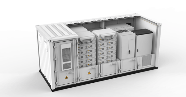
Not every project needs every item shown above. A smaller system may connect to an existing low-voltage board. A larger system may need several PCS units, a new transformer and medium-voltage switchgear. Some BESS products include these parts inside one package, while others require them to be supplied separately.
| Item | What mainly determines its rating | Common misunderstanding |
|---|---|---|
| Battery | How much energy must be stored and for how long | Assuming battery kWh determines transformer size |
| PCS | How much power the BESS can charge or discharge at one time | Looking only at kW and forgetting other grid duties |
| Transformer | How much power must pass through it and which voltages it must connect | Assuming every project simply needs 20% extra capacity |
| Switchgear | Normal current and the current that could occur during a fault | Selecting a breaker from normal current alone |
| Auxiliary supply | Power for cooling, controls, pumps, lights and safety systems | Forgetting that these devices also use electricity |
kWh is the fuel tank: it tells you how long the battery can keep going. kW is the useful pushing power: it tells you how much active power the system can move. kVA is the electrical carrying requirement: it includes both useful active power and reactive-power duty. Transformers and switchgear must be checked against that total electrical duty.
2. What Information Is Needed Before Sizing?
The BESS quotation alone is not enough. Before ordering a transformer or switchgear, collect three groups of information:
Maximum charging and discharging power, PCS voltage, number of PCS units and power used by cooling and controls.
Site voltage, current transformer loading, switchboard capacity, existing solar or generators and planned new equipment.
Import and export limits, zero-export requirements, backup operation and the local utility’s connection conditions.
The design input package should normally include:
- Maximum continuous BESS charge and discharge power at the AC boundary
- PCS rated voltage, frequency, kVA limit and active/reactive capability curve
- Whether grid rules require operation away from unity power factor
- Maximum coincident auxiliary load and where that load is supplied
- Facility load data, preferably including interval demand and operating scenarios
- Existing and proposed single-line diagrams with cable lengths and conductor data
- Utility source fault level or sufficient source data for the short-circuit study
- Existing transformer rating, impedance, vector group, tap position, loading and condition
- Ambient temperature, altitude, indoor or outdoor location, enclosure and ventilation
- Applicable grid code, equipment standards and network-operator settings
If the site is still deciding the battery power and duration, use the 15-minute load data guide for C&I BESS sizing first. Transformer selection begins after the required AC power and operating cases are reasonably defined.
3. How Large Should the BESS Transformer Be?
For an early estimate, follow five steps. The key idea is simple: calculate the highest amount of electrical power that may pass through the transformer, then check whether the transformer can carry it under the real site conditions.
Step 1: Check the busiest realistic condition
Look at charging and discharging separately. The highest import may happen when the factory is busy and the battery is charging. The highest export may happen when factory demand is low but the battery and solar system are both sending out power. Use realistic combinations, not an automatic total of every nameplate.
Step 2: Convert kW into the transformer’s carrying requirement
Transformers are normally rated in kVA, not kW. If the BESS kW and required power factor are known, use:
If active and reactive power are specified independently, use:
In plain English, the transformer may need to carry more electrical load than the useful kW figure suggests. A 500 kW PCS at a power factor of 0.95 requires about 526 kVA, not 500 kVA.
Step 3: Add the electricity used by the BESS itself
Cooling, pumps, controls, lighting and fire-safety equipment also use power. Add them when they are supplied through the same transformer, but do not add them twice if the BESS supplier has already included them.
Step 4: Allow for the real installation
Do not simply add 10%, 20% or 25% to every project. Hot weather, high altitude, limited ventilation, daily cycling and future expansion can change the usable transformer capacity. Use the transformer’s verified data for the actual site.
Step 5: Check the details that can change the answer
The engineer and transformer supplier should also confirm:
- Voltage ratio and tap range: matched to the PCS operating window and actual grid voltage
- Impedance: affecting voltage regulation and available fault current
- Vector group and grounding: coordinated with protection, zero-sequence behavior and the site earthing design
- Harmonic and converter duty: based on PCS data and the required power-quality study
- No-load and load losses: important because a BESS may cycle power through the transformer every day
- Charging and discharging duty: both power-flow directions must be included in the operating cases
- Inrush and energization: coordinated with breaker capability, relay settings and grid requirements
- Environment: temperature, altitude, humidity, pollution, seismic requirement, noise and fire strategy
Dry-type or liquid-filled transformer?
Neither type is automatically better for every BESS. A dry-type transformer may suit an indoor installation or a project that places a high priority on containing liquid, while a liquid-filled unit may be considered for outdoor or higher-duty applications. The real choice depends on rating, losses, temperature rise, fire strategy, ventilation, noise, footprint, maintenance, environmental containment, local rules and the supplier’s verified design. Compare the complete installed solution rather than choosing from one label.
Is a separate isolation transformer always required?
No. A two-winding step-up transformer may already provide galvanic separation between the PCS side and the grid side. Whether the project needs that arrangement—or any additional isolation transformer—depends on the PCS topology, grounding method, protection concept, leakage-current behavior, grid-operator requirements and locally adopted rules. Confirm the required function on the single-line diagram before adding a second transformer or assuming that a transformerless connection is acceptable.
4. Simple Example: A 500 kW BESS Connecting to 11 kV
Suppose a factory wants to connect a 500 kW BESS with a 400 V PCS to an 11 kV network. This is how the early estimate works:
- Maximum PCS active power: 500 kW
- Required operating power factor at that point: 0.95
- Coincident auxiliaries supplied through the same transformer: 20 kVA
- PCS-side voltage: 400 V, three phase
- Grid-side voltage: 11 kV, three phase
A. Convert 500 kW into kVA
B. Add the BESS cooling and control load
The calculated requirement is about 546 kVA, so a 630 kVA transformer may be considered for the preliminary plan. This does not mean every 500 kW BESS should use 630 kVA. The engineer must still check the actual PCS, site conditions and grid requirements.
C. See how voltage changes the current
| Side | Calculation | Approximate current |
|---|---|---|
| 400 V side | 630,000 ÷ (√3 × 400) | 909 A |
| 11 kV side | 630,000 ÷ (√3 × 11,000) | 33 A |
The same power produces about 909 A at 400 V but only about 33 A at 11 kV. That is why larger systems are often connected at medium voltage: it reduces current and cable size. The trade-off is additional transformer, switchgear, protection work and grid approval.
The 630 kVA selection must not be copied into another project. A different PCS voltage, grid-code reactive requirement, auxiliary arrangement, ambient condition or overload duty can change the answer. Breaker settings and short-circuit ratings cannot be obtained from this example.
5. Can the BESS Use the Site’s Existing Transformer?
Sometimes—but “transformer nameplate minus current peak load” is not a reliable answer by itself. The BESS changes the transformer’s duty in both directions and across many operating conditions.
| Operating case | What to calculate | Why it matters |
|---|---|---|
| Maximum site load + BESS charging | Highest transformer import kVA | Charging can create a new facility peak or overload |
| Minimum site load + BESS discharging | Maximum reverse flow or export | The connection agreement may limit or prohibit export |
| PV maximum + BESS discharging | Combined generation at the connection point | Solar and storage can exceed a shared export boundary |
| Peak shaving | Transformer loading before and after dispatch | The BESS may reduce utility-transformer loading during peaks |
| Grid outage or island mode | Source, grounding and fault behavior | Backup operation requires a separately engineered topology |
| Future expansion | New production, HVAC, EV charging and BESS modules | Unused nameplate capacity today may already be reserved |
Review interval load data, transformer temperature or loading history where available, equipment condition, impedance, protection settings and the utility agreement. If the BESS uses zero-export control, also define what happens when the meter or communication link fails. The EMS should not be treated as permission to exceed a transformer’s physical rating.
6. What Does the Low-Voltage Switchgear Need to Handle?
Switchgear is the equipment that connects, disconnects and protects the electrical circuit. It must safely carry normal current and also deal with a fault. The normal-current calculation is only the starting point.
Check normal operating current
Calculate the current for every PCS feeder and for the combined bus. Use the maximum apparent power, not only kW at unity power factor. Then confirm:
- Assembly rated current and group rated current where applicable
- Breaker frame rating, sensor or trip rating, and required adjustability
- Busbar, cable and termination temperature limits
- Manufacturer derating for the installed enclosure and ambient conditions
- Neutral rating where the selected topology and harmonic conditions make it relevant
- Isolation, maintenance access and the required form of internal separation
Check what happens during a fault
A short circuit can create a much larger current for a brief time. The switchgear must survive that current and disconnect it safely. The available fault current can come from the grid, transformers, large motors, generators and the PCS, so the final rating requires a project calculation.
A simple transformer-only sanity check is sometimes written as:
For the 630 kVA, 400 V example, if the transformer impedance were 6%, the transformer-only estimate would be about 15.2 kA. This is not the final site fault current because it ignores upstream impedance, cable impedance, other sources and the detailed behavior of inverter-based equipment. The 2026 edition of IEC 60909-0 provides the standardized calculation framework for three-phase AC systems where it is adopted.
The ampere number tells you about normal load current. It does not tell you whether the breaker can safely interrupt a 20 kA, 36 kA or larger fault, whether the assembly can withstand that fault for the required time, or whether upstream and downstream devices will trip in the correct order.
7. What Changes When the BESS Connects at Medium Voltage?
Medium-voltage current may look small—as the 33 A result in the example shows—but this does not make the equipment simple. The engineer still needs to specify:
- Rated voltage and insulation level for the network
- Rated normal current
- Rated short-time withstand current and duration
- Peak withstand or making duty
- Circuit-breaker or switch-fuse arrangement
- Earthing switch, interlocks and safe isolation sequence
- Loss-of-service-continuity and partition requirements where applicable
- Internal arc classification when required by the owner, local rules or risk assessment
- CT and VT ratios, accuracy classes, burdens and metering ownership
- Cable termination, surge protection, earthing and utility-visible isolation
IEC 62271-200 applies to AC metal-enclosed switchgear above 1 kV and up to 52 kV within its scope. It does not replace the network operator’s connection rules or the project’s protection study. For example, the utility may specify relay functions, communications, trip circuits, visible isolation, metering and witness tests beyond the basic equipment standard.
8. Should You Reuse, Share or Add a Transformer?
| Option | Possible advantage | Main engineering concern |
|---|---|---|
| Use the existing site transformer | Lower equipment and civil-work scope | Loading headroom, reverse power, protection changes, warranty, condition and export limits |
| Share a new transformer with PV or loads | Can consolidate infrastructure | Coincident operating cases, control hierarchy and combined import/export boundary |
| Dedicated BESS transformer | Clearer ownership, metering, protection and equipment duty | Additional CAPEX, footprint, losses, approvals and maintenance |
| Multiple smaller transformers or skids | Modularity and possible redundancy | More feeders, protection zones, interfaces and parallel-operation analysis |
There is no universally best arrangement. A retrofit with spare LV capacity may favor an existing board. A larger project, a site with weak LV infrastructure or a project requiring independent metering may justify a dedicated MV connection. Decide from the site single-line diagram, operating scenarios, outage strategy and lifecycle cost—not from a generic power threshold.
9. Which Checks Must the Electrical Engineer Complete?
The early numbers help with budgeting, but they are not a finished design. Before equipment is manufactured, the project team may need these checks:
- Load-flow study: checks import, export, voltage and equipment loading across operating scenarios
- Short-circuit study: establishes fault duty for switchgear, cables and protection
- Protection coordination study: defines relay and breaker settings so the correct device clears a fault
- Grounding study: confirms fault paths, touch and step conditions, bonding and the selected transformer connection
- Harmonic or power-quality study: checks distortion and resonance at the relevant connection point
- Arc-flash assessment: where required by the adopted workplace rules and design practice
- Cable ampacity and voltage-drop study: includes installation method, grouping and temperature
- Dynamic or grid-compliance study: where the grid operator requires voltage, frequency, reactive or fault-ride-through performance
IEEE 519-2022 defines harmonic-control goals at the point of common coupling in its scope. For U.S. projects, IEEE 1547.9-2022 provides guidance on applying IEEE 1547 to energy-storage DER interconnection. Other countries use different codes and approval processes, so the project specification must identify the locally adopted requirements rather than present one regional standard as global law.
10. What Should the Buyer Ask the Supplier to Provide?
| Document or value | What the buyer should require |
|---|---|
| Design basis | Charge, discharge, reactive-power, auxiliary, backup and expansion scenarios |
| Single-line diagram | Clear ratings, ownership boundaries, protection zones, metering points and cable interfaces |
| Transformer datasheet | kVA, voltage ratio, taps, impedance, vector group, losses, cooling, temperature rise, sound and environmental conditions |
| LV switchgear schedule | Assembly and feeder current, fault rating, breaker details, form of separation, IP rating and interlocks |
| MV switchgear schedule | Voltage, normal current, short-time and peak duty, breaker, earthing switch, CT/VT, relay and internal-arc requirement |
| Protection philosophy | Functions, zones, CT/VT inputs, trip matrix, settings responsibility and utility interface |
| Study inputs and reports | Agreed models, source data, assumptions and approved study revisions |
| Factory tests | Applicable routine and type-test evidence, FAT scope, interfaces, interlocks and witness requirements |
| Site tests | Insulation, grounding, ratio, polarity, relay injection, breaker timing, trip tests, meter direction and functional commissioning |
| Handover | As-built drawings, settings files, test records, manuals, spare parts and maintenance responsibilities |
The transformer, PCS and switchgear suppliers should use the same design basis. A common failure is to procure each package from a different revision of the single-line diagram, leaving mismatched current ratings, CT ratios, cable terminals, trip voltages or communication responsibilities to be discovered during commissioning.
Use the BESS FAT, SAT and final acceptance checklist to carry the approved design into testing. For long-term responsibilities after energization, see the BESS operation and maintenance guide.
11. Ten Common Mistakes to Avoid
- Sizing from battery MWh: transformer and switchgear duty follows AC power and operating conditions.
- Assuming kW equals kVA: reactive-power requirements can raise apparent power without raising active power.
- Applying a fixed oversizing percentage: margin must have a documented reason and should not replace derating calculations.
- Ignoring charging: maximum import can be more restrictive than maximum discharge.
- Ignoring minimum site load: discharge can create reverse power or violate a zero-export agreement.
- Selecting breakers from amperes alone: fault interruption and withstand ratings are separate checks.
- Forgetting auxiliaries: cooling and safety systems can create meaningful continuous and standby loads.
- Using outdated single-line diagrams: existing transformer, switchboard and cable data must match field conditions.
- Leaving protection until commissioning: CTs, VTs, relay functions and trip circuits affect procurement.
- Treating one country’s standard as global: the adopted code and utility rules must be confirmed for every destination.
12. What to Send PVB for a Project-Specific Review
- Required BESS power in kW and usable energy in kWh
- At least 12 months of interval load data when the system serves an operating facility
- Existing and proposed single-line diagrams
- Site and connection voltage, frequency, transformer data and switchboard data
- Maximum import/export, zero-export or grid-support requirements
- Solar, generator, UPS, EV charging and major motor information
- Ambient temperature, altitude, installation location and destination country
- Required backup loads, transfer sequence and operating duration, if applicable
PVB can then match the battery and PCS configuration to the project’s defined AC boundary and coordinate the required interfaces with the EPC and local electrical designer. Final transformer, switchgear, protection and grid approval remain project-specific.
Explore the PVB commercial and industrial energy storage solution or compare physical formats in Battery Storage Container vs. Battery Storage Cabinet.
- PCS
- Power Conversion System—the bidirectional equipment that converts between battery DC and site AC.
- kVA
- Kilovolt-amperes—apparent power, used when checking the total electrical carrying duty.
- kvar
- Kilovolt-amperes reactive—the reactive component of AC power.
- Power factor
- The relationship between active power and apparent power under the defined operating condition.
- Impedance
- Opposition to AC current; transformer impedance affects voltage regulation and available short-circuit current.
- CT / VT
- Current transformer / voltage transformer—measurement devices used by protection relays and meters.
- PCC
- Point of Common Coupling—the defined interface used for certain grid and power-quality requirements.
- FAT / SAT
- Factory Acceptance Test / Site Acceptance Test.
13. FAQ: BESS Transformer and Switchgear Sizing
Is a 1 MW BESS always paired with a 1 MVA transformer?
No. At unity power factor, 1 MW equals 1 MVA, but required reactive power increases apparent power. Auxiliaries, environmental derating, cyclic duty, overload requirements and future expansion can also change the transformer rating. Final selection must use the PCS capability and project operating cases.
Does battery capacity in MWh affect transformer size?
Not directly. MWh determines energy duration, while the PCS kW and kVA determine the maximum AC power passing through the transformer. Battery duration can affect how long the transformer carries high load, so it matters to the thermal duty even though it is not the transformer rating formula.
Can a BESS connect to an existing low-voltage switchboard?
Yes, when the board, transformer, cables, protection and utility service are suitable for the proposed current and fault conditions. The project must also check import, export, voltage drop, protection coordination and the combined operation of existing loads and generation.
How do I calculate BESS switchgear current?
For a balanced three-phase system, divide apparent power in VA by √3 times line-to-line voltage. Use the maximum kVA operating case. Then apply the assembly and equipment manufacturer’s installation and environmental requirements; the calculated current is not by itself the final switchgear rating.
What short-circuit rating does BESS switchgear need?
The switchgear must have ratings suitable for the prospective fault current and clearing time at its installation point. The answer comes from a site-specific short-circuit study using utility, transformer, cable, motor, generator and inverter data. Normal operating current cannot determine the required interrupting rating.
Does a BESS transformer need to be bidirectional?
A transformer can transfer AC power in either direction, but the project specification must evaluate both charging and discharging cases, including voltage regulation, taps, losses, protection, metering, grounding and thermal duty. The complete installation—not merely the transformer—must be designed for the intended bidirectional operation.
When should a C&I BESS connect at medium voltage?
There is no global kW threshold. Medium voltage may become practical when low-voltage current, cable runs, existing board capacity, connection rules or project scale make an LV connection unsuitable. The network operator and qualified designer should decide using the actual site topology and lifecycle cost.
14. References
Standards and grid rules change. Confirm the edition adopted by the destination country, network operator and authority before design or procurement. The links below lead to official standard pages used to verify titles, editions and published scope; full standard documents may require purchase or licensed access.
- IEC 60076-1:2011 — Power transformers, Part 1: General (accessed September 4, 2026).
- IEC 60076-11:2018 — Dry-type transformers (accessed September 4, 2026).
- IEC 61439-1:2020 — Low-voltage switchgear and controlgear assemblies, general rules (accessed September 4, 2026).
- IEC 61439-2:2020 — Power switchgear and controlgear assemblies (accessed September 4, 2026).
- IEC 60947-2:2024 — Low-voltage circuit-breakers (accessed September 4, 2026).
- IEC 62271-200:2021 — AC metal-enclosed switchgear above 1 kV and up to 52 kV; see the 2024 amendment where adopted (accessed September 4, 2026).
- IEC 60909-0:2026 — Short-circuit currents in three-phase AC systems (accessed September 4, 2026).
- IEEE 1547.9-2022 — Guide for interconnection of energy storage DER (accessed September 4, 2026).
- IEEE 519-2022 — Harmonic control in electric power systems (accessed September 4, 2026).